Menu
Menu
 Úvodní strana
Pažící systém Stratex firmy Hyduke
The Stratex Drill System (SDS) is an overburden drilling system designed for conditions where a cased hole is required. Collapsing holes tend to make overburden drilling expensive, with lost drilling equipment and down time.
 |  |  |
In cooperation with drillers and drilling contractors, the SDS was developed to overcome these problems. The patented eccentric design and the Drop Off Ring (DOR) drill bits enable the drill string and casing to be lowered in the hole simultaneously with a conventional hammer drilling system.
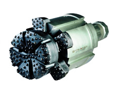
The SDS eccentric designed bit rotates outward and drills a larger diameter hole than the casing, avoiding cave-ins, wash-outs, and other problems common in normal drilling operations in soft and gravel-type strata or loose rock. Since 90% of the world's overburden drilling is in loose strata, potential utilization of the SDS is enormous.
After reaching the designated depth, the SDS reamer-bit is retracted by reversing the direction of the rotation and by applying tension on the reamer-bit, which has a taper and will retract into the casing for easy removal of the entire drill-string. This leaves the casing in place for other applications or for removal at a later date. The SDS method is designed for use with flush joint threaded pipe or welded-type casing and provides a bit size for a wide variety of different casing wall thicknesses.
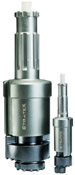
The PATENTED Stratex Eccentric under reamer system: 1. One-piece shank and guide device manufactured from the highest quality material with stringent quality control.
2. Air jets are used to prevent any malfunction of the opening and retraction of the reamer pilot bit operation and the clearing of cuttings above the reamer pilot bit system.
3. Sealed bearing system for ease in rotating the eccentric bit outward or retracting it into the casing.
4. Casing with shoe: Casing may be supplied with plain or threaded ends.
5. Grooved bypass directly above the lock system to clear cuttings and ensure complete drilling face contact.
6. Tapered shoulder on the reamer bit eliminates casing binding and assists in the retracting of the reamer bit into the casing.
7. One-piece reamer and pilot bit manufactured from the highest quality material, with stringent quality control.
8. Gauge protection carbides on heavy duty, one-piece pilot and reamer bit.
9. Dome carbides on heavy duty pilot and reamer bit.
The Stratex System utilizes a one-piece reamer and pilot bit that moves outward to full open position on an eccentric shaft by rotating a half turn to the right. This reamer pilot bit system opens a larger diameter hole than the diameter of the casing. The casing is simultaneously lowered into the hole as the reamer pilot bit drills. The pilot bit is rotated at 10 to 40 rpm while drilling with the hammer. When the designated drilling depth is reached, the reamer pilot bit system is retracted into the casing by applying slight tension and reversing the direction of the drilling rotation. The design of the reamer pilot bit system incorporates a closed bearing method that makes the loss of the pilot bit virtually impossible. This bit system, in the closed position, is easily removed through the casing shoe and casing. | ||
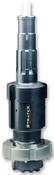
Working
| Retracted
| 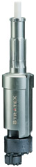 |
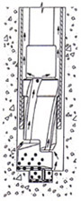

Assembly of the Stratex System The Stratex Drilling Method is used with air rotary drilling rigs and most manufacturers' downhole hammers. The drill rod is connected to the rig top drive using a changeover sub or swivel sub. The drill rod is then connected to the down-hole hammer by the same method. The chuck nut and split rings are removed to insert the guide device shank and secured by replacing the split rings and chuck nut. The reamer bit, in the closed position, is now inserted into the casing shoe. Since the percussion hammer is at the bottom of the hole, working directly above the drill bit, the force to pull down the casing tube is transferred by way of the casing shoe. The exhaust air from the drill redirects the loose cuttings up through the groves on the guide device, forcing them up between the drill rod and the casing wall out through the discharge head, which is attached to the casing tube. By using a discharge head, drilling is not only safer but also environmentally cleaner. Stratex can be used with foam or water to aid in cutting removal. 1. One-piece reamer and pilot bit | 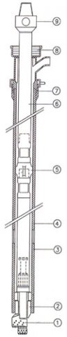 |
Good Flushing
Good Flushing is essential with any successful drilling operation or in using an overburden drilling system. The Stratex System provides air jets above and below the guide device, creating a vacuum across the face of the reamer bit, removing the cuttings with greater annular velocity. The gauge carbides along the side of the pilot and reamer bit act to crush the cuttings into finer particles, the majority of which are removed from the hole. The remaining cuttings are forced back into the walls of the cavity, leaving less material to be extracted from the hole.
Air velocity is important for efficient hole cleaning. A minimum return air velocity of 4000 feet per minute is desirable. Annular space between drill pipe and the drilled hole as well as compressor capacity determines the air velocity. The annular air velocity in foot per minute can be calculated with the following formula if air consumption and annular area are known:
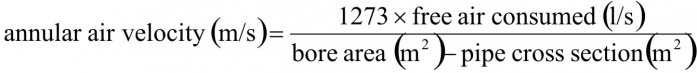 |
The following flushing mediums are also useful:
Air with water injection
Air with foam injection
NOTE: Foam has the ability to lift cuttings and stabilizes the wall of the hole and provides lubrication for easier casing penetration. Foam also has good drilling performance in most types of clay.
Telescopic Drilling
Using a telescoping drilling method can achieve deeper depths.
| Some string samples are as follows: | 365 | 240 | 190 | 140 | 90 |
| 365 | 215 | 165 | 115 | ||
| 365 | 215 | 140 | 90 |
Hole Depth
Casing depths with Stratex can reach 500 feet or more with the down-hole hammer versions depending on the type of formation, drilling equipment, and drilling personnel experience.
| Stratex System (mm) | 70 | 80 | 90 | 115 | 140 | 165 | 190 |
| Normal Max - Hole Depth (m) | 61 | 76 | 91 | 152 | 152 | 152 | 152 |
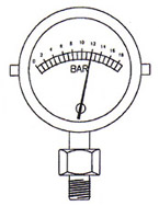 | Recommended Maximum Air Pressure for Stratex Drill Systems The maximum recommended air pressure for Stratex drilling with down-hole hammers is 12 bar, which equals 210 psi. Rotation speed depends on the size of the Stratex bit and the formation being drilled. The rotation speed may have to be varied as the formation changes. The table shows recommended rotation speeds for the various Stratex sizes. |
Recommended Rotation Speeds
| Stratex System (mm) | 70 | 80 | 90 | 115 | 140 | 165 | 190 | 215 | 240 | 280 |
| Speed (rpm) | 20-40 | 10-25 | ||||||||
Minimum Torque
Drill rigs must have sufficient torque for drilling with Stratex. The table shows recommended rotation speeds for the various Stratex bit sizes.
| Stratex System (mm) | 70 | 80 | 90 | 115 | 140 | 165 | 190 | 215 | 240 | 280 |
| Minimum Torgue (lb/ft) | 570 | 600 | 663 | 1470 | 2200 | 2950 | 4000 | 4000 | 4000 | 7000 |
| Minimum Torgue (N.m) | 772 | 812 | 898 | 1991 | 2979 | 3995 | 5417 | 5417 | 5417 | 9480 |
Stratex Over Burden Drilling Tool: Size and Technical Chart (inch)
Tool Size | Casing Sizes | Drive Shoe I.D. (B) | Drive Shoe Length (C) | Guide to Casing Distance (D) | Reamed Diameter (E) | Bit Size (F) | Guide to Casing Distance (D) | |
O.D. (A) | Walls (S) | |||||||
70 | 3.50 | .216 | 2.750 | 2.5 | 4.25 | 3.75 | 2.75 | 2.968 |
80 | 4.0 | .237 | 3.156 | 2.75 | 4.5 | 4.375 | 3 | 3.437 |
90 | 4.5 | .247 | 3.650 | 3.5 | 5 | 5 | 3.5 | 3.937 |
110 | 5.562 | .375 | 4.375 | 5.5 | 7.50 | 6.125 | 4.25 | 4.75 |
115 | 5.562 | .258 | 4.575 | 5.5 | 7.50 | 6.125 | 4.25 | 4.937 |
132 | 6.625 | .432 | 5.188 | 5 | 7.75 | 7.5 | 4.875 | 5.593 |
140 | 6.625 | .280 | 5.575 | 5 | 7.75 | 7.5 | 5.125 | 5.937 |
142 | 7 | .498 | 5.575 | 5 | 7.625 | 7.875 | 5.25 | 5.875 |
150 | 7 | .272 | 5.937 | 5 | 7.625 | 7.875 | 5.25 | 6.375 |
160 | 7.625 | .500 | 6.036 | 5.5 | 8.25 | 8.75 | 6.125 | 6.500 |
165 | 7.625 | .301 | 6.575 | 5.5 | 8.25 | 8.75 | 6.25 | 6.937 |
180 | 8.625 | .500 | 7.075 | 6 | 8.75 | 10 | 6.75 | 7.535 |
190 | 8.625 | .277 | 7.575 | 6 | 8.75 | 10 | 7.375 | 7.937 |
200 | 9.625 | .500 | 7.937 | 6 | 9 | 11 | 7.625 | 8.437 |
210 | 9.625 | .342 | 8.312 | 6 | 9 | 11 | 8 | 8.845 |
215 | 10 | .250 | 8.625 | 6 | 9 | 11 | 8 | 9.250 |
230 | 10.75 | .500 | 9.050 | 7 | 10.25 | 11.75 | 8.75 | 9.625 |
235 | 10.75 | .365 | 9.275 | 7 | 10.25 | 11.75 | 9 | 9.890 |
250 | 11.75 | .500 | 10 | 7 | 10.75 | 13.25 | 9.625 | 10.62 |
260 | 11.75 | .375 | 10.25 | 7 | 10.75 | 13.25 | 10 | 10.87 |
280 | 12.75 | .500 | 10.937 | 7 | 11 | 14.5 | 10.625 | 11.56 |
Stratex Over Burden Drilling Tool: Size and Technical Chart (mm)
Tool Size | Casing Sizes | Drive Shoe I.D. (B) | Drive Shoe Length (C) | Guide to Casing Distance (D) | Reamed Diameter (E) | Bit Size (F) | Guide to Casing Distance (D) | |
O.D. (A) | Walls (S) | |||||||
70 | 88.9 | .216 | 2.750 | 2.5 | 4.25 | 3.75 | 2.75 | 2.968 |
80 | 101.6 | .237 | 3.156 | 2.75 | 4.5 | 4.375 | 3 | 3.437 |
90 | 114.3 | .247 | 3.650 | 3.5 | 5 | 5 | 3.5 | 3.937 |
110 | 141.3 | .375 | 4.375 | 5.5 | 7.50 | 6.125 | 4.25 | 4.75 |
115 | 141.3 | .258 | 4.575 | 5.5 | 7.50 | 6.125 | 4.25 | 4.937 |
132 | 168.3 | .432 | 5.188 | 5 | 7.75 | 7.5 | 4.875 | 5.593 |
140 | 168.3 | .280 | 5.575 | 5 | 7.75 | 7.5 | 5.125 | 5.937 |
142 | 177.8 | .498 | 5.575 | 5 | 7.625 | 7.875 | 5.25 | 5.875 |
150 | 177.8 | .272 | 5.937 | 5 | 7.625 | 7.875 | 5.25 | 6.375 |
160 | 193.7 | .500 | 6.036 | 5.5 | 8.25 | 8.75 | 6.125 | 6.500 |
165 | 193.7 | .301 | 6.575 | 5.5 | 8.25 | 8.75 | 6.25 | 6.937 |
180 | 219.1 | .500 | 7.075 | 6 | 8.75 | 10 | 6.75 | 7.535 |
190 | 219.1 | .277 | 7.575 | 6 | 8.75 | 10 | 7.375 | 7.937 |
200 | 244.5 | .500 | 7.937 | 6 | 9 | 11 | 7.625 | 8.437 |
210 | 244.5 | .342 | 8.312 | 6 | 9 | 11 | 8 | 8.845 |
215 | 250.4 | .250 | 8.625 | 6 | 9 | 11 | 8 | 9.250 |
230 | 273.0 | .500 | 9.050 | 7 | 10.25 | 11.75 | 8.75 | 9.625 |
235 | 273.0 | .365 | 9.275 | 7 | 10.25 | 11.75 | 9 | 9.890 |
250 | 298.5 | .500 | 10 | 7 | 10.75 | 13.25 | 9.625 | 10.62 |
260 | 298.5 | .375 | 10.25 | 7 | 10.75 | 13.25 | 10 | 10.87 |
280 | 323.8 | .500 | 10.937 | 7 | 11 | 14.5 | 10.625 | 11.56 |


 +420 774 292 308
 info@vrtaci-technika.cz